
[Ed. Note- Lindsay Porter's DIY Guide also has a chapter detailing step-by-step how to rebuild the MGB front suspension with lots of pictures. If you are unsure about how to proceed, I heartily recommend this book.]
Rebuilding the front suspension or replacing individual components on an MGB is not as difficult as one would imagine. If you can change your brakes then you have the skill to work on your suspension. When one thinks of suspension work they think of heavy duty tools and back breaking work. Nothing could be further from the truth.
The tools that you will need to do the job will be a set of 1/2 sockets, a pair of pliers, a tie rod separator, possibly a breaker bar, a floor jack, some jack stands and a torque wrench. There are least seven jobs that can be done together, or you may choose to do only one at a time.
The seven tasks are as follows:
- Replace all the rubber bushings
- Replace the springs
- Replace the shocks
- Replace the swivel axle assembly (king pins)
- Repack or replace the wheel bearings
- Replace the brake pads
- Replace the brake rotors
MGB Front Crossmember and Suspension Parts Diagram, courtesy Moss Motors
MGB Front Suspension Removal Steps
For clarification I will use the Moss catalog numbers.
- Before jacking the car up, remove the top bolt on the drop link (3). Once removed you can then jack up the car. Remove the road wheels and place it on jack stands. If you are using the common technique of compressing the springs using a floor jack, then it's important to get the car high enough off the ground so that the spring pan (13) can droop to fully vertical. If you do not get the car up high enough, you will run into problems when refitting the springs.
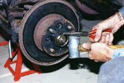
- Remove the two bolts that hold the brake caliper on. Remove the brake pads and support the caliper so as not to damage the brake line.
- Loosen, but do not completely remove the nut (33) that attaches the
swivel axle to the shock absorber. Position the nut on the end of the bolt
to protect the threads and tap it with a hammer until it comes out. Once the
bolt is out the swivel axle will drop forward and the spring can be slowly
lowered with the jack.
This may turn out to be easier said than done since there are several factors that can make it difficult if not impossible to remove the bolt. It is important to make sure that the bolt is not being pushed out of alignment by the force of the jack. If after few minutes of hammering you are unable to free the trunnion bolt, you probably won't be able to remove it.
If this is the case you will need to cut the bolt. The easiest method is to use an angle grinder with a cut off wheel. A saw will work but even an electric saw will take considerably longer. If you pry away the bearings (34) (actually they are bushings) you will see the bolt. You will have to make two cuts on the end where the head is in order to have clearance. - Then after cutting the nut off you should be able to drift out the remainder of the bolt inside the trunnion (22), or at least provide clearance between the swivel axle and the shock arms. With the top of the swivel axle free it should now be possible to pull the swivel axle towards you.
- At this point the spring is loaded and dangerous. For safety's sake, attach the spring to the car with a cable or chain to stop the spring should it slip. Slowly lower the jack until the spring can be removed.
- The bolt (41) that holds the bottom of the swivel axle can seize up inside the distance tube (44) and cause the same problem as the upper bolt. If this is the case remove the two nuts (49) on the pivot (15) at the rear of the wishbone arms (11) as well as the nuts that hold the spring pan (41) together. This will free one wishbone arm from the swivel axle, the side with the nut. It will also allow you to remove the other wishbone arm so that you can work on it in a vice. Heat from a MAPP torch will be needed to push the bolt through the distance tube (44) enough to cut the end off.
- At this point the suspension is completely dissembled and the condition of the components should be apparent. Look at the wishbone arms and the spring pans to see if the if any of the holes are elongated. If so they should be replaced. If the hubs have been removed then take the opportunity to repack or replace the bearings and seals.
Rebuilding the Wheel Bearings
Given the effort required to get the hubs off and on, and the fact that no special tools are required, it makes sense to repack the bearings and replace the seals while things are apart.
- There are two sets of bearings in the front hub. The outer bearing will slip right out when the hub is removed.
- Look carefully on the back of the bearing for very thin pieces of metal that look like washers. These are the shims that allow the wheel to spin freely. The inner bearing is held in place with an oil seal. It is necessary to remove the seal in order to pack the bearing.
- To remove the seal, grab it with a pair of pliers and pull it towards the center of the hub. The seal will then be able to be pulled out with a little effort. Once the seal is removed the inner bearing will slip right out.
- It is not necessary to remove the bearing race if you only plan on cleaning the bearings. If on the other hand, if the bearings are going to be replaced then the race should also be replaced. The new bearing comes as a set with a race included so it will be easy to identify the existing race inside the hub if you are not sure what a race looks like.
- To remove the race, tap it out from the back side with a hammer and punch. You should be able to drive it out without any problem. Both bearings and the hub should be cleaned with kerosene and then dried.
- The inner bearing should be packed with grease prior to putting the hub back onto the car. The front packing should wait until the preliminary shimming has been done. To repack the inner bearing, put the bearing in the palm of your hand and squeeze plenty of grease into the front and back of the bearing as well as around the bearing, don't be concerned with over packing it. When the bearing is completely packed place it back into the race.
- To replace the seal, lay a large diameter steel washer on top of it and gently tap it down with a hammer. If the race is being renewed you can use a steel washer to drive it in. Doing it this way you will also need a heavy bolt about 3 inches long to reach inside the hub and two nuts to hold the washer onto the bolt. Sandwich the washer between the two nuts with one nut in front of the washer and one behind the washer.
- Once the seal has been replaced you should fill the gap between the seal and bearing with grease.
Although this may sound complicated it shouldn't take more than an hour for the whole job, which includes replacing the races and seals.
MGB Front Suspension Reassembly
- The first item to install will be the uprated V8 bushings (52) on the wishbone arms. The area at the end of the wishbone arm where the bushing goes needs to be cleaned out, and the simplest method is to lightly sand it smooth.
- Next, coat both the bushing and the inside of the wishbone arm with liquid soap. Place the bushing and wishbone arm in a vice and close the jaws until the bushing is about 3/4 of the way through the wishbone arm. Then place a large socket between the jaw of the vice and the wishbone arm and continue to squeeze until there is an equal amount of rubber sticking out of both side of the arm.
- The wishbone arms are now ready to reinstall. Using a parts diagram, check to be sure that all the washers, etc are being placed in the correct order. Assemble the rear of the wishbone arms, then the spring pan, and finally the swivel axle assembly. Final tightening will be done when the car is on the ground.
- Reinstalling the springs can be somewhat time consuming if you are using the jacking method. First be sure that the car is high enough off the ground to allow the spring pan to placed in a completely vertical position. Now place the spring up into the area of the suspension being careful that it is centered. With the jack centered under the spring pan, and the spring secured with a cable, slowly start jacking up the spring pan. If all goes well the swivel axle should raise high enough to attach the top bolt to the shock absorber lever arms.
- The most common problem with this method is that the jack will not be able to raise the swivel axle high enough. If you are within about 1/2 inch try pushing down on the shock arm to line things up. If you are more than 1/2 inch off then you will need to lower the car somewhat. At this point two jacks will prove to be invaluable.
- As an alternative, take a second set of jack stands and place one on each side of the spring pan. Then, with a very strong pipe, support the spring pan by placing the pipe under the pan with the ends of the pipe supported by the jack stands. Having done this you should now be able to remove the jack from the spring pan and reposition it the center of the front cross member.
- With the jack supporting the weight of the car, the jackstands that are holding the car, not the spring, can now be removed. Once these stands are removed the car can be slowly lowered, which will cause the spring pan which is being supported by the pipe to slowly rise. Once the swivel axle and the shock arm are lined up loosen the bolt in the center of the shock arm that holds the arm together and gently pry them apart. The swivel axle should now slide in.
Even with difficulty, this should only take about 45 minutes per side to accomplish. Although it may sound complicated it will become apparent what needs to be done once work begins.
After the suspension has been put back together the only task that remains it to install the hubs and brakes. Adjusting the hubs is straight forward as explained in the Moss catalog. What you want to achieve is a free spinning hub without any wobble.
One final step before you are done is to lower the car, bounce it a few times and then torque everything up. Check ever nut and make sure that new cotter pins have been installed were needed. Take the car to an alignment shop and then enjoy your new ride.
[Ed. Note- Torque settings and additional notes can be found in this tech article]

")


Also, the grease retaining cup (part 662-030), the part that goes into the wire wheel hub to cover the bearing retaining nut, will not fit a new hub. You must grind the edges down so it can slip fit the hub. The bolt that sticks out of it is tack welded on and is a poor design. While trying to trial fit the cup to the hub, the bolt welds gave way. I replaced the welded stud with a conventional nut and bolt. That bolt is imortant when you need to remove the grease cup so it needs to be strong.
Just thought I'd pass these tips along to anyone else rebuilding their front end.
Ciao for now.......Bruno
Front shock absorber bolts: 44 ft lbs
Brake caliper mounting bolts: 43 ft lbs
Hub nut, align to next hole: 40 ft lbs
Crossmember to body nuts: 55 ft lbs
Shock absorber pinch bolt: 28 ft lbs
Lower arm nuts, align to next
Split pin hole: 28 ft lbs
Lower arm/spring pan nuts: 22 ft lbs
Stabilizer bar link nut: 60 ft lbs
Swivel pin nut, align to next
Split pin hole: 60 ft lbs
Steering arm bolts: 63 ft lbs
Steering tie rod locknuts: 35 ft lbs
Steering rack to crossmember: 30 ft lbs
Disc brake rotor to hub: 43 ft lbs
Road wheel lug nuts (Bolt on wheels): 60 to 65 ft lbs
from thread:
,http://www.mgbexperience.com/phorum/read.php?1,377478>
Want to leave a comment or ask the owner a question?
Sign in or register a new account — it's free